Get started with ESP32 and Arduino
In this guide you will learn how to play with the Arduino framework and the ESP32 microcontroller of your new UDOO KEY board.
It is quite easy since it works like any other ESP32 based board.
First of all, let's download and install the Arduino IDE following the official documentation.
Now you have to properly setup the IDE in order to use it with the board.
Leave the jumper labeled with Serial Sel open, to drive the USB communication to the ESP32 and connect the board to your PC using a USB cable.
The connected device will be discovered by your PC as COM8 port in Windows OS or as /dev/ttyUSB0 device in Linux based OSs.
Check the correct port or device before continuing.
Once the port has been found, open the IDE and follow the instructions below to add the ESP32 support to the board manager.
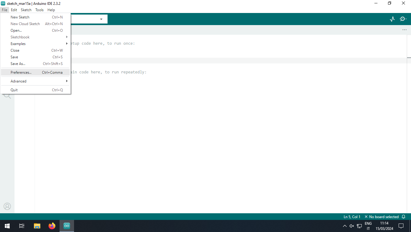
Open Preferences window by selecting File and then Preferences....
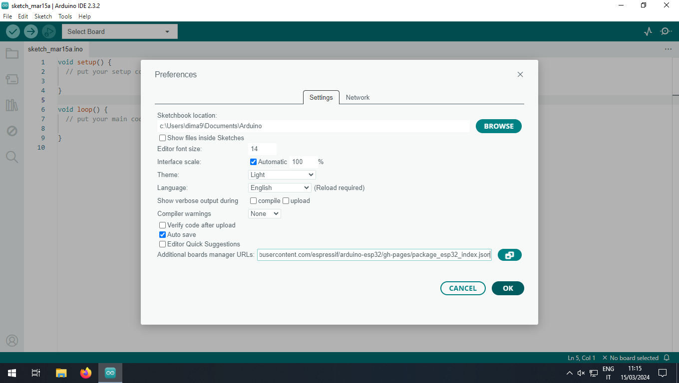
On the Settings tab, insert the URL https://raw.githubusercontent.com/espressif/arduino-esp32/gh-pages/package_esp32_index.json in Additional boards manager URLs field and then click on the OK button.
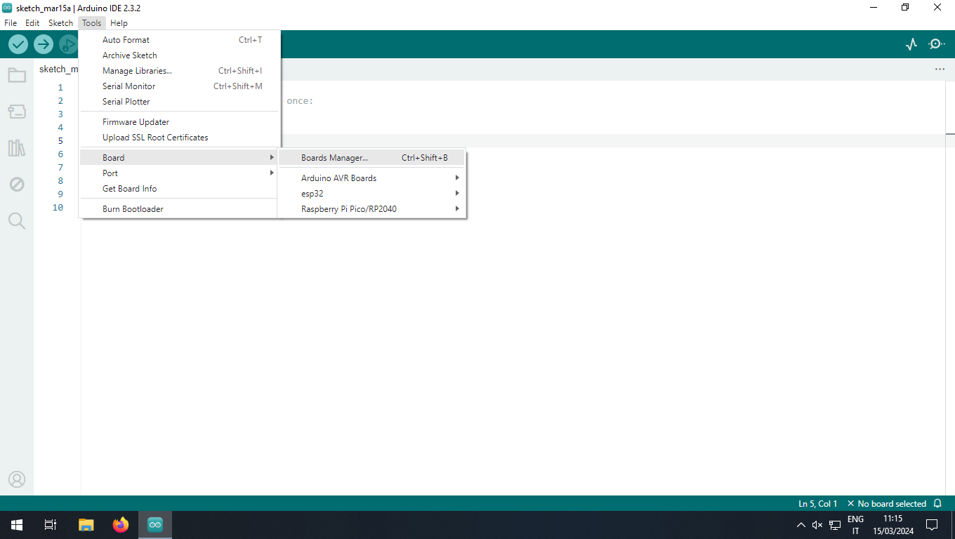
Install the ESP32 board support from the Boards Manager by selecting Tools, Board and Boards Manager....
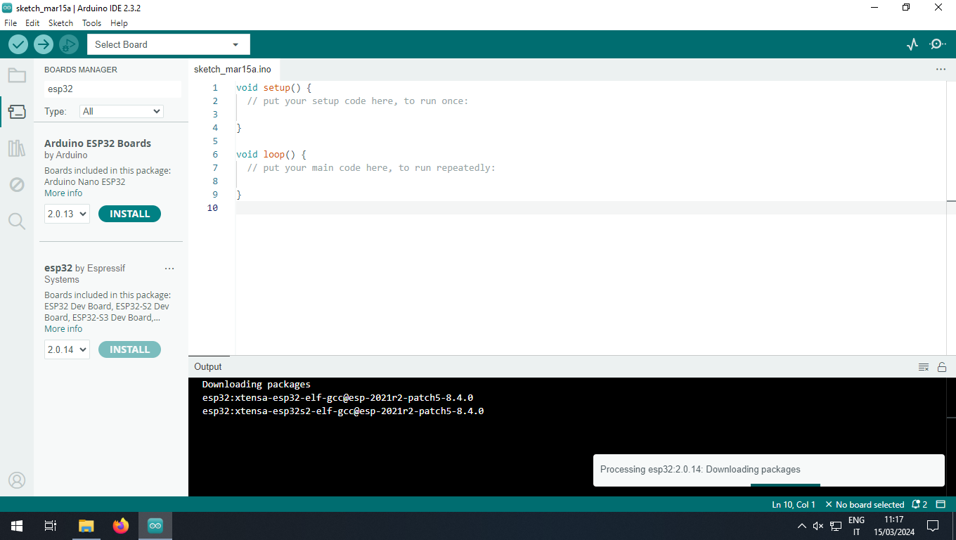
Search the esp32 text and, among the filtered results, select esp32 by Espressif Systems and click the INSTALL button.
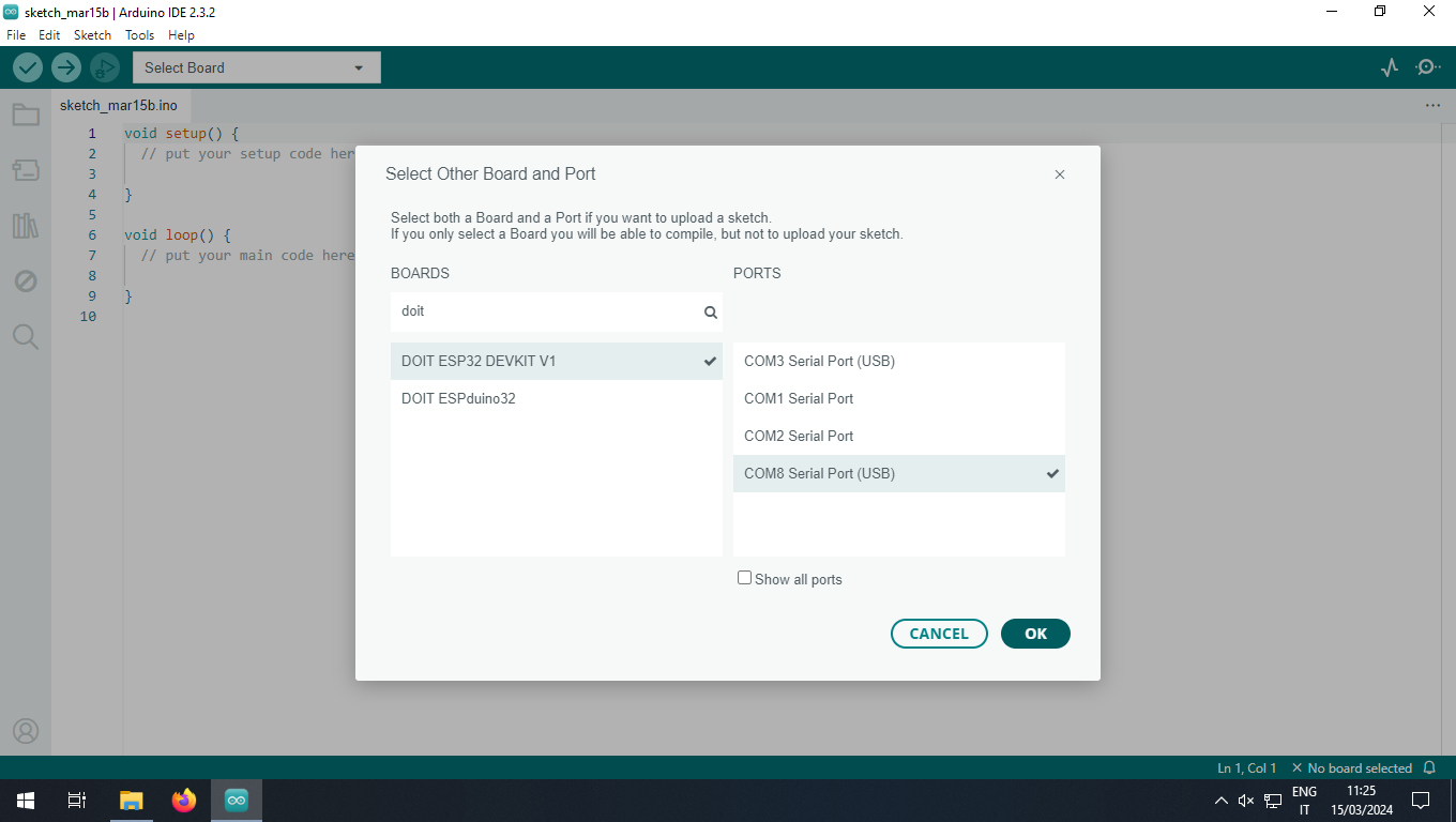
When the installation has finished, select the correct connected board and its port, depending on the OS.
On Windows it will be something like COM8 (use the Device Manager to find the correct one) and on Linux based OSs you will have a device file like /dev/ttyUSB0.
Now choose the example you want to load on the microcontroller clicking on File, Examples and then on the project.
In this guide we will flash the Blink sketch from the 01.Basics sub-menu.
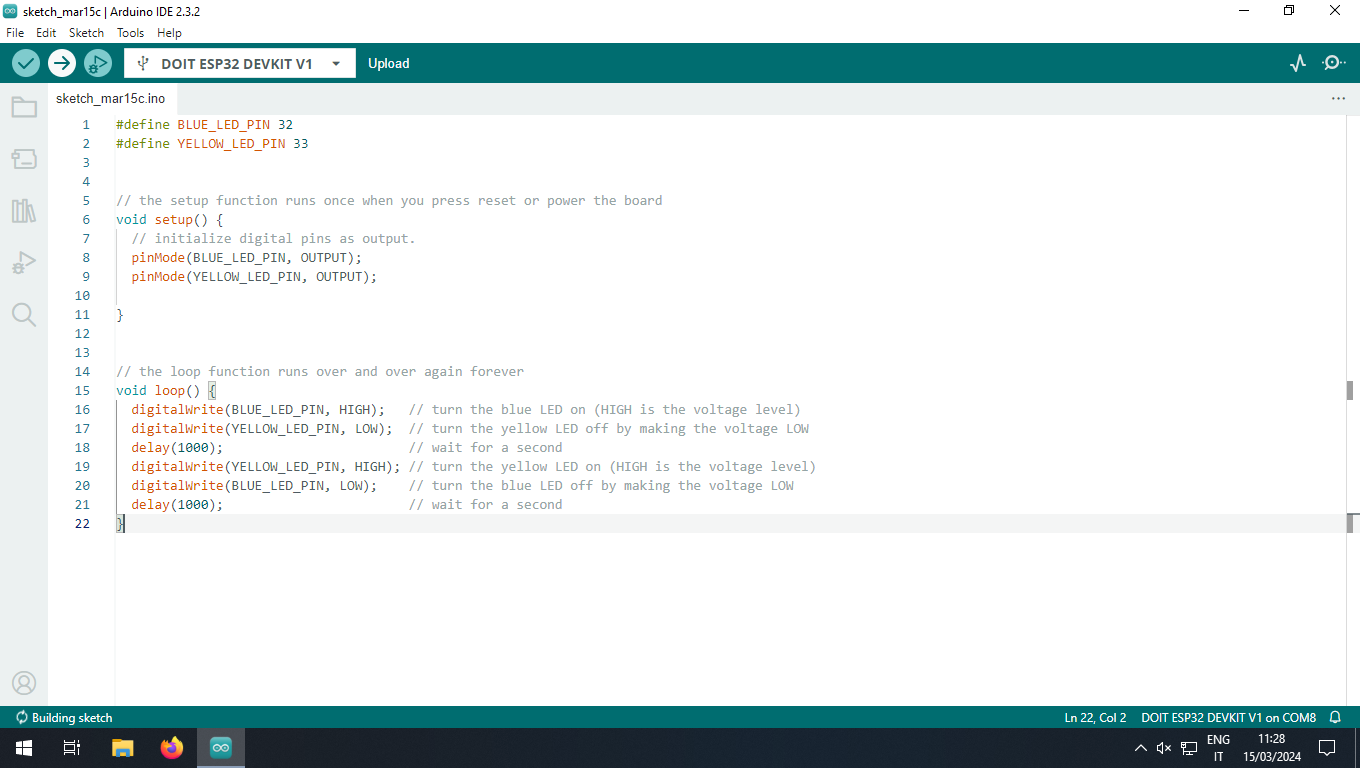
In order to blink alternatively the two on-board LEDs connected to the ESP microcontroller, some changes have to be applied on the original source code. The final code is:
#define BLUE_LED_PIN 32
#define YELLOW_LED_PIN 33

// the setup function runs once when you press reset or power the board
void setup() {
  // initialize digital pins as output.
  pinMode(BLUE_LED_PIN, OUTPUT);
  pinMode(YELLOW_LED_PIN, OUTPUT);
}

// the loop function runs over and over again forever
void loop() {
  digitalWrite(BLUE_LED_PIN, HIGH);   // turn the blue LED on (HIGH is the voltage level)
  digitalWrite(YELLOW_LED_PIN, LOW);  // turn the yellow LED off by shifting the voltage LOW
  delay(1000);                        // wait for a second
  digitalWrite(YELLOW_LED_PIN, HIGH); // turn the yellow LED on (HIGH is the voltage level)
  digitalWrite(BLUE_LED_PIN, LOW);    // turn the blue LED off by shifting the voltage LOW
  delay(1000);                        // wait for a second
}
Differently from the RP2040 microcontroller, you must put the ESP32 in flash mode by closing the jumper JP2 and pressing reset button before upload the firmware.
After that, you can upload the sketch to the microcontroller by clicking the "Upload" button.
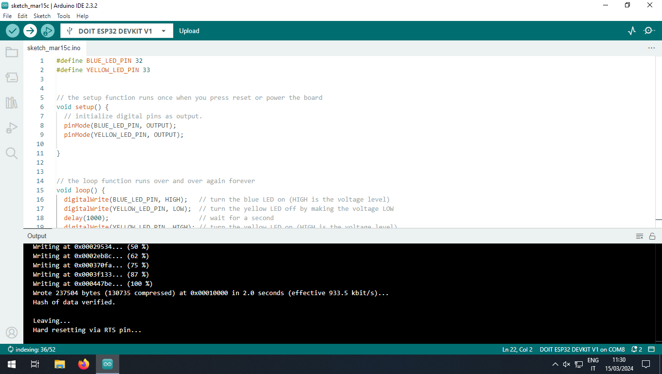
Once the upload has finished, you must manually reset the MCU to see the LEDs blinking.