GPIOs
The GPIO (General-Purpose Input/Output) peripheral provides dedicated general-purpose pins that can be configured as either inputs or outputs. When configured as an output, it is possible to write to an internal register to control the state driven on the output pin. When configured as an input, it is possible to detect the state of the input by reading the state of an internal register. In addition, the GPIO peripheral can produce CORE interrupts.
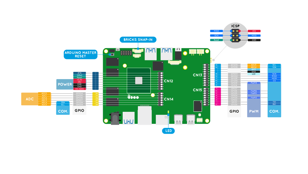
UDOO X86 features a total of 36 GPIOs available on the external Pinout connectors.
- 16 GPIOs are available in the external Pinout columns manageable from the main Intel® Braswell processor of the UDOO X86. These Pins are 1.8V only compliant.
- 20 GPIOs are available in the internal Arduino Pinout columns manageable from the Intel® Curie™ processor of the Arduino 101 embedded. These Pins are 3.3V compliant and 5V tollerant.
Select the tab accordingly to which Processing Unit you want use to manage the related GPIOs.
Curie™ GPIOs (Arduino 101)
In the following image you can see in grey labels the 20 GPIOs manageable from the main Intel® Curie™(Arduino 101-compatible embedded).
Refer to the Arduino 101 (Intel Curie) section to manage the Arduino GPIOs. You will be able to use the internal row pinout exactly like you do with an Arduino 101.
Braswell GPIOs
In this section you can see how to use the 16 GPIOs manageable from the main Intel® Braswell processor of the UDOO X86.
The Linux driver used to manage the UDOO X86 Braswell GPIOs is Cherryview/Braswell pinctrl driver.
Since the Linux Kernel version 4.15 the driver has changed the number associated to each GPIOs managable by the external pinout of the UDOO X86.
Linux Kernel version 4.15 is the default one in Ubuntu 18.04 LTS distro.
Chose the TAB accordingly with the Linux Kernel version are you using.
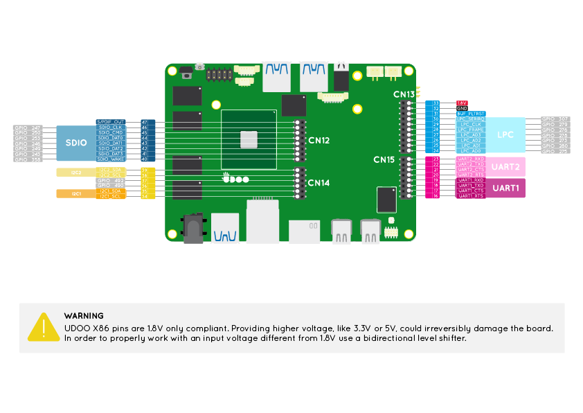
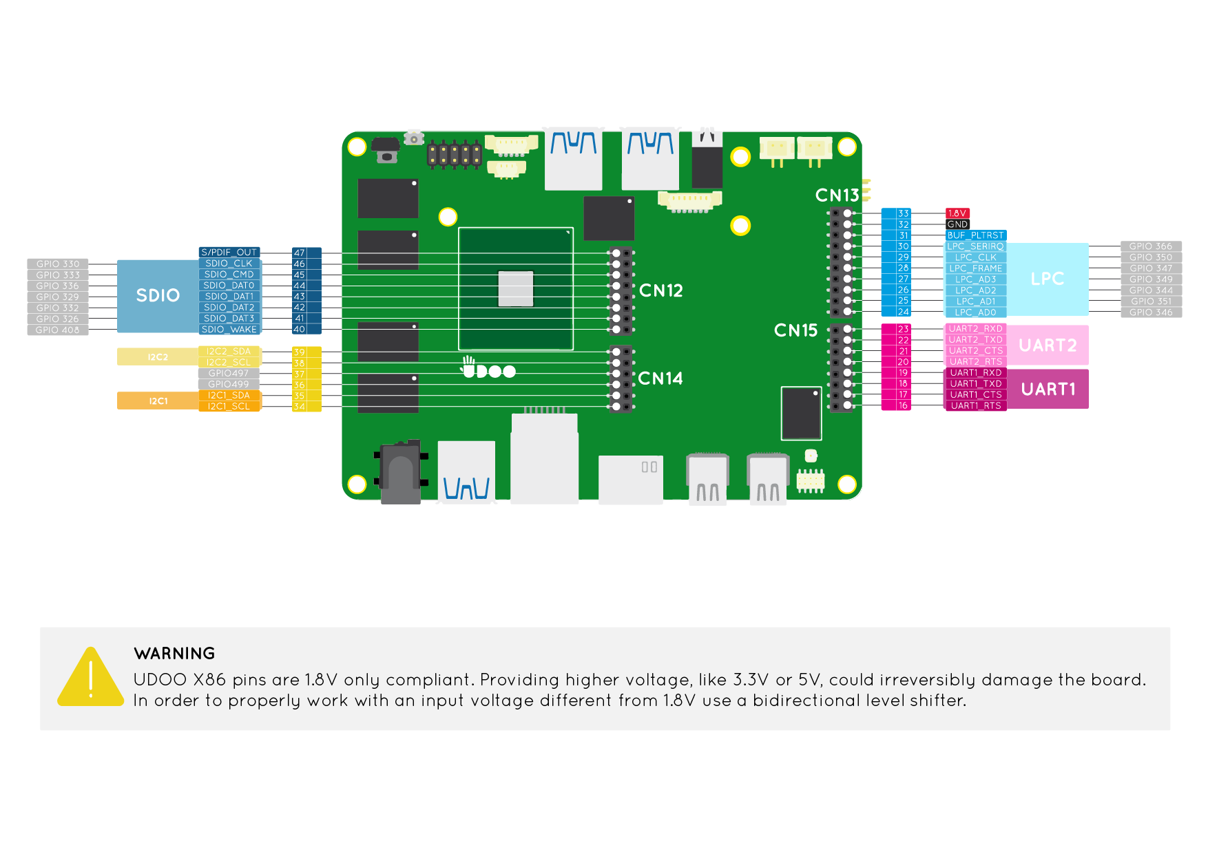
In the following image you can see in grey labels the 16 GPIOs manageable from the main Intel® Braswell.
Visit the Pinout Braswell section to see how to enable/disable the GPIO function for these pins from the UEFI BIOS Setup of the UDOO X86.
The GPIO function is enabled by default in the UEFI BIOS Setup configuration of the UDOO X86.
Take a look at this exhaustive guide How to use 1.8V serial on UDOO X86 with 3.3V-5V devices by Geduino Foundation to learn how to proper use a level shifter to work with a different voltage from 1.8V in the Braswell pinout.
Linux Manipulation
The Linux driver used to manage the UDOO X86 Braswell GPIOs is Cherryview/Braswell pinctrl driver
In the following tables you can find GPIO numbers assigned by the driver to each Pin that can act as GPIO. In the UDOO forum you can check the correct procedure to find the correct GPIO number assigned to each Pin explained in this post by fajar.adianto.
PinHeader Connector CN13
| Physical Pin Number | GPIO NUMBER | GPIO device name from the Linux Driver |
|---|---|---|
| 24 | 275 | /sys/class/gpio/gpio275 |
| 25 | 280 | /sys/class/gpio/gpio280 |
| 26 | 273 | /sys/class/gpio/gpio273 |
| 27 | 278 | /sys/class/gpio/gpio278 |
| 28 | 276 | /sys/class/gpio/gpio276 |
| 29 | 279 | /sys/class/gpio/gpio279 |
| 30 | 307 | /sys/class/gpio/gpio307 |
PinHeader Connector CN14
| Physical Pin Number | GPIO NUMBER | GPIO device name from the Linux Driver |
|---|---|---|
| 36 | 490 | /sys/class/gpio/gpio490 |
| 37 | 492 | /sys/class/gpio/gpio492 |
PinHeader Connector CN12
| Physical Pin Number | GPIO NUMBER | GPIO device name from the Linux Driver |
|---|---|---|
| 40 | 358 | /sys/class/gpio/gpio358 |
| 41 | 243 | /sys/class/gpio/gpio243 |
| 42 | 249 | /sys/class/gpio/gpio249 |
| 43 | 246 | /sys/class/gpio/gpio246 |
| 44 | 253 | /sys/class/gpio/gpio253 |
| 45 | 250 | /sys/class/gpio/gpio250 |
| 46 | 247 | /sys/class/gpio/gpio247 |
For those users are still using a Linux Kernel version previous the 4.15 we are still maintaining here the old tables and images with the GPIOs numbers not updated.
In the following image you can see in grey labels the 16 GPIOs manageable from the main Intel® Braswell.
Visit the Pinout Braswell section to see how to enable/disable the GPIO function for these pins from the UEFI BIOS Setup of the UDOO X86.
The GPIO function is enabled by default in the UEFI BIOS Setup configuration of the UDOO X86.
Take a look at this exhaustive guide How to use 1.8V serial on UDOO X86 with 3.3V-5V devices by Geduino Foundation to learn how to proper use a level shifter to work with a different voltage from 1.8V in the Braswell pinout.
Linux Manipulation
The Linux driver used to manage the UDOO X86 Braswell GPIOs is Cherryview/Braswell pinctrl driver
In the following tables you can find GPIO numbers assigned by the driver to each Pin that can act as GPIO.
PinHeader Connector CN13
| Physical Pin Number | GPIO NUMBER | GPIO device name from the Linux Driver |
|---|---|---|
| 24 | 346 | /sys/class/gpio/gpio346 |
| 25 | 351 | /sys/class/gpio/gpio351 |
| 26 | 344 | /sys/class/gpio/gpio344 |
| 27 | 349 | /sys/class/gpio/gpio349 |
| 28 | 347 | /sys/class/gpio/gpio347 |
| 29 | 350 | /sys/class/gpio/gpio350 |
| 30 | 366 | /sys/class/gpio/gpio366 |
PinHeader Connector CN14
| Physical Pin Number | GPIO NUMBER | GPIO device name from the Linux Driver |
|---|---|---|
| 36 | 497 | /sys/class/gpio/gpio497 |
| 37 | 499 | /sys/class/gpio/gpio499 |
PinHeader Connector CN12
| Physical Pin Number | GPIO NUMBER | GPIO device name from the Linux Driver |
|---|---|---|
| 40 | 408 | /sys/class/gpio/gpio408 |
| 41 | 326 | /sys/class/gpio/gpio326 |
| 42 | 332 | /sys/class/gpio/gpio332 |
| 43 | 329 | /sys/class/gpio/gpio329 |
| 44 | 336 | /sys/class/gpio/gpio336 |
| 45 | 333 | /sys/class/gpio/gpio333 |
| 46 | 330 | /sys/class/gpio/gpio330 |
Here you can find the Driver Documentation in the kernel that explain the use of the sysfs inferface.
Export GPIOs
In /sys/class/gpio folder there are two files that allow you to export pins for access and unexport pins to remove access.
/sys/class/gpio/export
/sys/class/gpio/unexport
To export a GPIO so that we can read, write and control the pin, we simply write the GPIO_NUMBER to the export file:
echo GPIO_NUMBER > /sys/class/gpio/export
For example, to export GPIO 307:
echo 307 > /sys/class/gpio/export
Once GPIO pin 307 is exported the following files (or links to files) are created in a new directory, gpio307.
/sys/class/gpio/gpio307/direction
/sys/class/gpio/gpio307/value
A GPIO can be set in input or output configuration.
In input means you can read the value of the voltage connected to the pins.
In output means you can forces a pin to take a specific voltage.
It is possible to switch a GPIO in input or output mode by writing either in or out to the direction file:
# set gpio 307 to input
echo in > /sys/class/gpio/gpio307/direction

# set gpio 307 to output
echo out > /sys/class/gpio/gpio307/direction
To verify the voltage direction, just read the same file:
cat /sys/class/gpio/gpio307/direction
Write values
To write a low or high value on a GPIO, you need to write 0 or 1 in the value file:
# set gpio 307 to low value - 0 volts
echo 0 > /sys/class/gpio/gpio307/value

# set gpio 307 to high value - 1.8 volts
echo 1 > /sys/class/gpio/gpio307/value
In order to set the value, the GPIO must be in the out direction.
Read values
If the direction is set to in, it is possible to read the GPIO value reading the same value file:
cat /sys/class/gpio/gpio307/value
If the direction is set to out and you try to read the value, is not guaranteed that the value is coherent with the voltage found on the external pinout.