Pinout Braswell
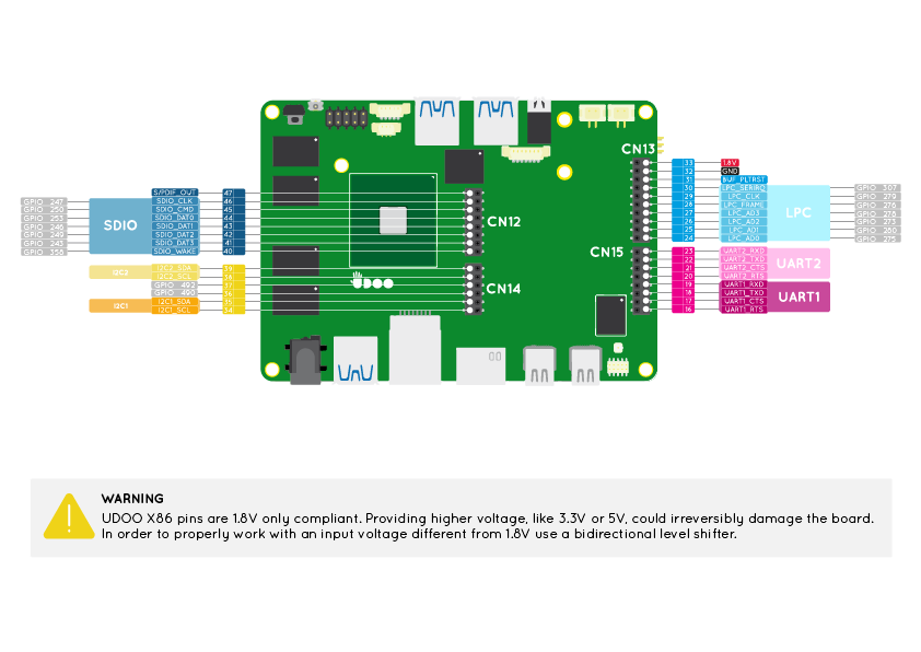
The external row Pinout headers (Pins from 16 to 47) are connected to the Intel® Braswell x86 Processor of the UDOO X86.
Take a look at this exhaustive guide How to use 1.8V serial on UDOO X86 with 3.3V-5V devices by Geduino Foundation to learn how to proper use a level shifter to work with a different voltage from 1.8V in the Braswell pinout.
Pinmuxing
The image below shows the list of all possible functions assigned to each Pin.
UART 1 and UART 2
Universal Asynchronous Receiver/Transmitter (UART) provides serial communication capability with external devices through a level converter and an RS-232 cable or through the use of external circuitry that converts infrared signals to electrical signals (for reception) or transforms electrical signals to signals that drive an infrared LED (for transmission) in order to provide low speed IrDA compatibility.
The UART 1 is available at Pins 16, 17, 18, 19.
The UART 2 is available at Pins 20, 21, 22, 23.
Both these serials are High-Speed UART (HSUART).
Accordingly to the Braswell datasheet the baud rate goes from 300 to 3686400.
HSUART 1
| Pin | Function | Processor PAD |
|---|---|---|
| 16 | UART1_RTS | UART1_RTS_B |
| 17 | UART1_CTS | UART1_CTS_B |
| 18 | UART1_TXD | UART1_TXD |
| 19 | UART1_RXD | UART1_RXD |
HSUART 2
| Pin | Function | Processor PAD |
|---|---|---|
| 20 | UART2_RTS | UART2_RTS_N |
| 21 | UART2_CTS | UART2_CTS_N |
| 22 | UART2_TXD | UART2_TXD |
| 23 | UART2_RXD | UART2_RXD |
These Pins can't work as GPIOs.
These two HSUART buses are enabled by default. You can Enable/Disable the UART 1 and UART 2 from the UEFI BIOS Setup by changing the configuration set in the section:
Advanced
--> Chipset configuration
    --> LPSS & SCC Configuration

        LPSS Configuration
        DMA #1 Support          <Enabled (ACPI)>
          HSUART #1             <Enabled (ACPI)>
          HSUART #2             <Enabled (ACPI)>
Use the UART in Linux
The UART 1 and UART 2 are shown respectively as /dev/ttyS4 and /dev/ttyS5 when configured as HSUART mode(default configuration). If you can't find this two serial in Linux, you probably need to disable the Virtual COM option in the BIOS menu (Can be changed only when HSUART #1 and HSUART #2 are Enabled). If Disabled, the Virtual COM won't be added to the ACPI table.
The UART 1 and UART 2 are shown respectively as /dev/tty0 and /dev/tty1 when configured in Legacy mode.
Use the UART in Windows 10
To use the UARTs in Windows, after enabling them in BIOS Setup, you need to download the corresponding drivers.
Download and install the Intel Serial IO Driver. Then download the specific HSUART driver for UDOO X86.
Verify the presence of Unknown Device with Device ID as ACPI\VCOM000x or ACPI\INT351x in Windows Device Manager.
Extract the archive file, press mouse right-button on x64\UartSample.inf / x86\UartSample.inf (depending on the OS architecture) and select Install.
On Device Manager, one or more UartSample Device devices will appear under "Port (COM & LPT)" section.
Now the devices are ready and they can be used with a HSUART Virtual Serial Terminal like extraPuTTY.
LPC bus
LPC bus is a computer bus used to connect low-bandwidth devices such as serial and parallel ports, PS/2 etc.
Quoting the Wikipedia LPC page:
The Low Pin Count bus, or LPC bus, is a computer bus used on IBM-compatible personal computers to connect low-bandwidth devices to the CPU, such as the boot ROM, "legacy" I/O devices (integrated into a super I/O chip), and Trusted Platform Module (TPM).[2] "Legacy" I/O devices usually include serial and parallel ports, PS/2 keyboard, PS/2 mouse, and floppy disk controller.
The LPC bus is available at Pins 24, 25, 26, 27, 28, 29, 30.
This Pins can also work as GPIOs if the LPC bus function is disabled in the UEFI BIOS Setup.
| Pin | Function | Processor PAD | GPIO device name from the Linux Driver |
|---|---|---|---|
| 24 | LPC_AD0 | MF_LPC_AD0 | gpio346 |
| 25 | LPC_AD1 | MF_LPC_AD1 | gpio351 |
| 26 | LPC_AD2 | MF_LPC_AD2 | gpio344 |
| 27 | LPC_AD3 | MF_LPC_AD3 | gpio349 |
| 28 | LPC_FRAME | LPC_FRAME_N | gpio347 |
| 29 | LPC_CLK | MF_LPC_CLKOUT0 | gpio350 |
| 30 | LPC_SERIRQ | ILB_SERIRQ | gpio366 |
The LPC bus is disabled by default, so you can use these pins as GPIOs. You can Enable/Disable the LPC bus from the UEFI BIOS Setup by changing the configuration set in the section:
Advanced
--> Chipset configuration
    --> Miscellaneous Configuration

      LPC Support         <Disabled>
BUF_PLTRST
This is a power sequencing signal. This is used to report that the UDOO X86 is actually turned on and to get off from the reset state all the connected peripherals.
For example, if you connect to the board a new peripheral that supports reset state you can connect this Pin to the new peripheral reset pin. This way the new peripheral will be in reset when the board is in a deep suspend state (S3/S4/S5) and out of the reset state when the UDOO X86 is actually turned on, with a considerable power saving.
| Pin | Function | Processor PAD |
|---|---|---|
| 31 | PLTRST | PMU_PLTRST_N |
This Pin can't work as GPIO.
I2C 1 and I2C 2
The I2C (Inter-IC) bus is a bi-directional, two-wire serial bus that provides a communication link between integrated circuits (ICs). Phillips introduced the I2C bus 20 years ago for mass-produced items such as televisions, VCRs, and audio equipment. Today, I2C is the de-facto solution for embedded applications.
The I2C 1 is available at Pins 34, 35.
The I2C 2 is available at Pins 38, 39.
I2C1
| Pin | Function | Processor PAD |
|---|---|---|
| 34 | I2C1_SCL | I2C0_SCL |
| 35 | I2C1_SDA | I2C0_SCL |
I2C2
| Pin | Function | Processor PAD |
|---|---|---|
| 38 | I2C2_SCL | I2C5_SCL |
| 39 | I2C2_SDA | I2C5_SCL |
These Pins can't work as GPIOs.
These two I2C buses are enabled by default. You can Enable/Disable the I2C 1 and I2C 2 from the UEFI BIOS Setup by changing the configuration set in the section:
Advanced
--> Chipset configuration
    --> LPSS & SCC Configuration

        LPSS Configuration
        ...
        DMA #2 Support             <Enabled (ACPI)>
          I2C #1 - CN14 pin10/12   <Enabled (ACPI)>
          I2C #2 - CN14 pin2/4     <Enabled (ACPI)>
GPIOs pins
The Pins headers 36, 37, 40, 41, 42, 43, 44, 45, 46 can work as GPIOs only.
The GPIO function is enabled by default for these Pins.
| Pin | Function | Processor PAD | GPIO device name from the Linux Driver |
|---|---|---|---|
| 36 | GPIO | SATA_GP2 | gpio499 |
| 37 | GPIO | SATA_GP1 | gpio497 |
| 40 | GPIO | GPIO_SUS3 | gpio408 |
| 41 | GPIO | SDMMC2_D3_CD_N | gpio326 |
| 42 | GPIO | SDMMC2_D2 | gpio332 |
| 43 | GPIO | SDMMC2_D1 | gpio329 |
| 44 | GPIO | SDMMC2_D0 | gpio336 |
| 45 | GPIO | SDMMC2_CMD | gpio333 |
| 46 | GPIO | SDMMC2_CLK | gpio330 |
S/PDIF
S/PDIF (Sony/Philips Digital Interface Format) is a type of digital audio interconnect used in consumer audio equipment to output audio over reasonably short distances. The signal is transmitted over either a coaxial cable with RCA connectors or a fibre optic cable with TOSLINK connectors. S/PDIF interconnects components in home theatres and other digital high-fidelity systems.
The S/PDIF Output bus is available at Pin 47.
| Pin | Function | Processor PAD |
|---|---|---|
| 47 | SPDIF_OUT | AUDIO CODEC |
This Pin can't work as GPIO.
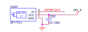
To use the S/PDIF bus you need to install a connector type TOSLINK or RCA.
The following is an example of a TOSLINK connector schematic: