 UDOO Quad/Dual Documentation
Device Tree Editor
Introduction
The device tree is a data structure used for describing hardware. The device tree is compiled by the device tree compiler (dtc), which produces binary .dtb files (also known as flattened device trees, or fdt).
The data structure is a tree of named nodes and properties and it can hold any kind of data. Nodes contain properties and child nodes, while properties are name–value pairs. More informations are available on here and here.
UDOObuntu provides out-of-the-box device tree blobs, available in /boot/dts/, for all possible combinations of board processor and screen type. This are the files you can usually find:
imx6q-udoo-hdmi.dtb
imx6q-udoo-lvds15.dtb
imx6q-udoo-lvds7.dtb
imx6dl-udoo-hdmi.dtb
imx6dl-udoo-lvds15.dtb
imx6dl-udoo-lvds7.dtb
The boot loader loads the correct dtb file, depending on the board and the chosen display.
Custom device trees
While the board can be used with the default device tree, which exports most of the external pins as GPIO, it is also possible to export more features on the external pinout. See the section GPIO Pinout to discover all the exportable configurations for the Cortex-A9 main Processor.
On UDOO QUAD/DUAL the external pins are shared between the two Processors and can be programmed one by one. The pins controlled by i.MX6 main processor can export different features (e.g. UART, PWM, I2C etc.)
UDOObuntu provides a graphical tool to change this configuration called Device Tree editor. Open if from the START menu -> Preferences -> Device Tree editor.
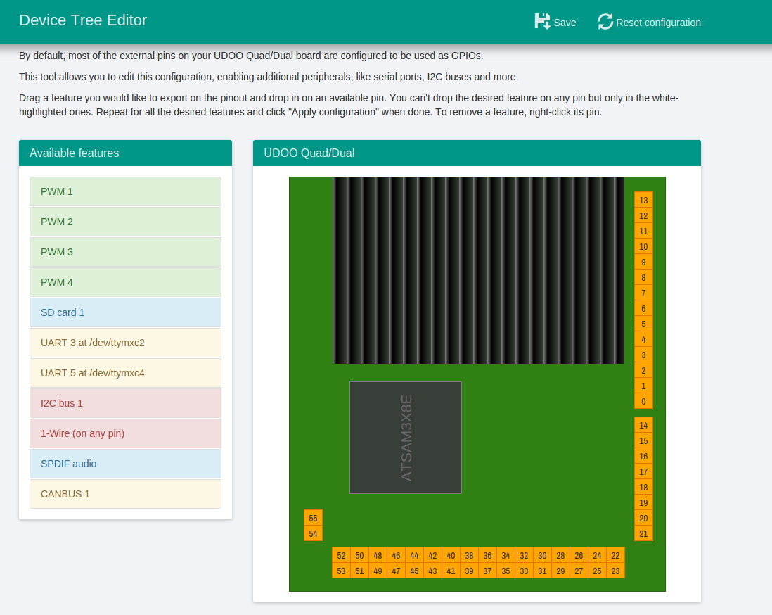
To remove the feature you need to right-click on a dark orange pin in the right panel.
After the functions are selected you can save by clicking on the top Save button, and then reboot the board.
The IOMUX
The i.MX processor has several pins, most of which have multiple signal options. These signal-to-pin and pin-to-signal options are selected by the input-output multiplexer called IOMUX. The IOMUX is also used to configure other pin characteristics, such as voltage level, drive strength and hysteresis.
i.MX 6 Quad/DualLite used in UDOO QUAD/DUAL boards implements many features and can export their signals on external pad. Each pad has no fixed signal but can be changed at boot depending on the needs of the manufacturer.

Every feature has one or more signals to implements its function and not all the feature can be exported at the same time on chip pads. Some of these pads are connected to external pins available to the user for connecting extra hardware or connections.