 UDOO Neo Documentation
RGB led
Description
The RGB color model is an additive color model in which red, green, and blue light are added together in various ways to reproduce a broad array of colors. The name of the model comes from the initials of the three additive primary colors, red, green, and blue.
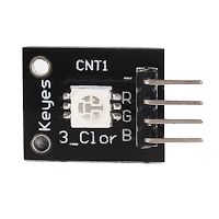
At first glance, RGB (Red, Green, Blue) LEDs look just like regular LEDs, however, inside the usual LED package, there are actually three LEDs, one red, one green and yes, one blue. By controlling the brightness of each of the individual LEDs you can mix pretty much any color you want.
They are called SMD 5050 because the dimensions of the chips are 5.0mm x 5.0mm.
RGB LEDs are Tri-color LEDs with red, green, and blue emitters, in general using a four-wire connection with one common lead (anode or cathode).
These LEDs can have either common positive or common negative leads. Others however, have only two leads (positive and negative) and have a built in tiny electronic control unit.
How does it work
A light-emitting diode (LED) is a two-lead semiconductor light source. It is a p–n junction diode, which emits light when activated. When a suitable voltage is applied to the leads, electrons are able to recombine with electron holes within the device, releasing energy in the form of photons. This effect is called electroluminescence, and the color of the light (corresponding to the energy of the photon) is determined by the energy band gap of the semiconductor.
Device information
5050 LED Specifications
- Red Vf: 1.8 to 2.1V
- Green Vf: 3.0 to 3.2V
- Blue Vf: 3.0 to 3.2V
- Red color: 620-625 nm
- Green color: 520-525 nm
- Blue color: 465-470 nm
- Red brightness @ ~20mA: 600-800 mcd
- Blue brightness @ ~20mA: 800-1000 mcd
- Green brightness @ ~20mA: 1500-2000mcd
Example
const int redPin = 11;  // R petal on RGB LED module connected to digital pin 11
const int greenPin = 10;  // G petal on RGB LED module connected to digital pin 9
const int bluePin = 9;  // B petal on RGB LED module connected to digital pin 10

void setup()
{
         // pinMode(redPin, OUTPUT); //  Unlike Arduino, no PWM pins declaration needed in UDOO NEO
         // pinMode(greenPin, OUTPUT);
         // pinMode(bluePin, OUTPUT);
}

void loop()  // run over and over again
{
          // Basic colors:
          color(255, 0, 0); // turn the RGB LED red
          delay(1000); // delay for 1 second
          color(0,255, 0); // turn the RGB LED green
          delay(1000); // delay for 1 second
          color(0, 0, 255); // turn the RGB LED blue
          delay(1000); // delay for 1 second
          // Example blended colors:
          color(255,0,0); // turn the RGB LED red
          delay(1000); // delay for 1 second
          color(237,109,0); // turn the RGB LED orange
          delay(1000); // delay for 1 second
          color(255,215,0); // turn the RGB LED yellow
          delay(1000); // delay for 1 second
          color(0,255,0); // turn the RGB LED green
          delay(1000); // delay for 1 second
          color(0,0,255); // turn the RGB LED blue
          delay(1000); // delay for 1 second
          color(0,46,90); // turn the RGB LED  indigo
          delay(1000); // delay for 1 second
          color(128,0,128); // turn the RGB LED purple
          delay(1000); // delay for 1 second
}

void color (unsigned char red, unsigned char green, unsigned char blue)     // the color generating function
{
          analogWrite(redPin, red);
          analogWrite(bluePin, blue);
          analogWrite(greenPin, green);
}