 UDOO Neo Documentation
Motion sensors
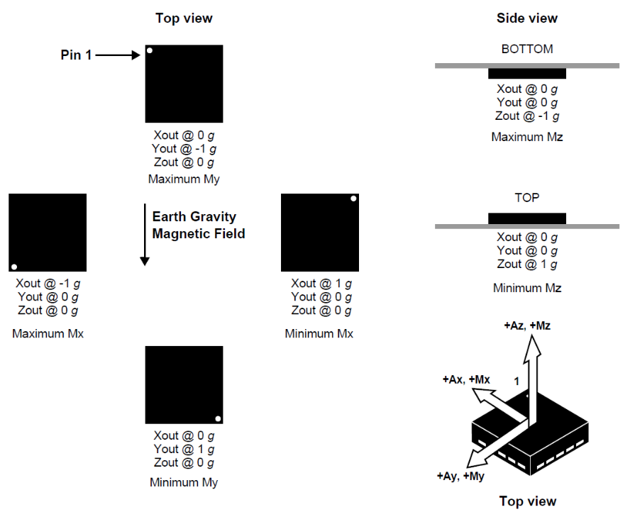
UDOO Neo is equipped with 9-axis motion sensors: accelerometer, magnetometer and gyroscope.
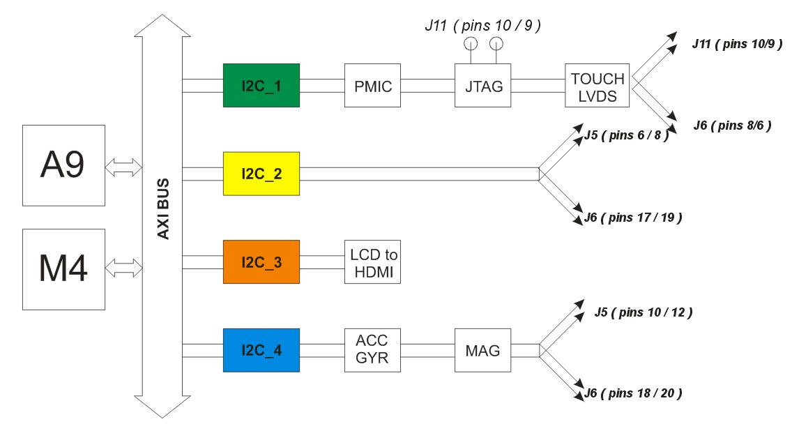
Accelerometer and magnetometer are embedded on the same Freescale chip, that is FXOS8700CQ, the gyroscope is a single FXAS21002C chip. They communicate with i.MX 6SoloX over I2C bus number 4.
They can be accessed by M4 core and also by A9 core. They can be used in ping mode, asking the values to the sensors, or in interrupt mode.
Heads up! Only EXTENDED and FULL board versions are equipped with embedded motion sensors.
FXOS8700CQ - Accelerometer/Magnetometer
FXOS8700CQ is a small, low-power, 3-axis, linear accelerometer and 3-axis, magnetometer combined into a single package. The device features an I2C with 14-bit accelerometer and 16-bit magnetometer ADC resolution along with smart-embedded functions.
FXOS8700CQ has dynamically selectable acceleration full scale ranges of ±2g / ±4g /±8g and a fixed magnetic measurement range of ±1200μT. Output data rates (ODR) from 1.563 Hz to 800 Hz are selectable by the user for each sensor. Interleaved magnetic and acceleration data is available at ODR rates of up to 400 Hz. FXOS8700CQ is guaranteed to operate over the extended temperature range of -40 °C to +85 °C.
- I2C address: 0x1E
- Download datasheet
Read acceleration and magnetic field data
To enable the accelerometer, you need to write 1 in the file below:
echo 1 > /sensors/accelerometer/enable
Heads up!In Udoobuntu versions higher or equals than 2 this sensor is enabled by default!
Accelerometer data is then available reading the file /sensors/accelerometer/data.
To enable the magnetometer, you need to write 1 in the file below:
echo 1 > /sensors/magnetometer/enable
Heads up!In Udoobuntu versions higher or equals than 2 this sensor is enabled by default!
Magnetometer data is then available reading the file /sensors/magnetometer/data.
FXAS21002 - Gyroscope
3-Axis Digital Angular Rate Gyroscope FXAS21002C is a small, low-power, yaw, pitch, and roll angular rate gyroscope with 16 bit ADC resolution. The full-scale range is adjustable from ±250°/s to ±2000°/s. It features I2C interface. FXAS21002C is capable of measuring angular rates up to ±2000°/s, with output data rates (ODR) from 12.5 to 800 Hz.
An integrated Low-Pass Filter (LPF) allows the host application to limit the digital signal bandwidth. The device may be configured to generate an interrupt when a user-programmable angular rate threshold is crossed on any one of the enabled axes. FXAS21002C is guaranteed to operate over the extended temperature range of –40 °C to +85 °C
- I2C address: 0x20
- Download datasheet
Read angular speed data
To enable the gyroscope, you need to write 1 in the file below:
echo 1 > /sensors/gyroscope/enable
Heads up!In Udoobuntu versions higher or equals than 2 this sensor is enabled by default!
Gyroscope data is then available from reading the file /sensors/gyroscope/data.
Examples
Accelerometer examples
#!/bin/bash
echo 1 > /sensors/accelerometer/enable
cat /sensors/accelerometer/data

# it will print something like:
# -6948,344,-14472
<?php
file_put_contents("1", "/sensors/accelerometer/enable");
$data = trim(file_get_contents("/sensors/accelerometer/data"));
$axis = explode(",", $data);
echo "X=" . $axis[0] . " Y=" . $axis[1] . " Z=" . $axis[2] . PHP_EOL;
echo "Modulus=" . sqrt($axis[0]*$axis[0] + $axis[1]*$axis[1] + $axis[2]*$axis[2]) . PHP_EOL;

// it will print something like:
// X=688 Y=-480 Z=-16436
// Modulus=16457.394690533
Magnetometer examples
#!/bin/bash
echo 1 > /sensors/magnetometer/enable
cat /sensors/magnetometer/data

# it will print something like:
# -225,257,1372
<?php
file_put_contents("1", "/sensors/magnetometer/enable");
$data = trim(file_get_contents("/sensors/magnetometer/data"));
$axis = explode(",", $data);
echo "X=" . $axis[0] . " Y=" . $axis[1] . " Z=" . $axis[2] . PHP_EOL;
echo "Modulus=" . sqrt($axis[0]*$axis[0] + $axis[1]*$axis[1] + $axis[2]*$axis[2]) . PHP_EOL;

// it will print something like:
// X=-412 Y=-414 Z=1348
// Modulus=1469.0963208721
Gyroscope examples
#!/bin/bash
echo 1 > /sensors/gyroscope/enable
cat /sensors/gyroscope/data

# it will print something like:
# 12,8,4
<?php
file_put_contents("1", "/sensors/gyroscope/enable");
$data = trim(file_get_contents("/sensors/gyroscope/data"));
$axis = explode(",", $data);
echo "X=" . $axis[0] . " Y=" . $axis[1] . " Z=" . $axis[2] . PHP_EOL;
echo "Modulus=" . sqrt($axis[0]*$axis[0] + $axis[1]*$axis[1] + $axis[2]*$axis[2]) . PHP_EOL;

// it will print something like:
// X=19 Y=13 Z=3
// Modulus=23.2163735
Direct I2C register access
It' also possible to read direcly from I2C register. However, for novice users we suggest to use previous methods.
Read accelerometer/magnetometer data via I2C
#!/bin/sh

# set to active mode
i2cset -f -y 3 0x1e 0x2a 1
# enable both accelerometer and magnetometer
i2cset -f -y 3 0x1e 0x5b 3

while [ 1 ]; do
  # accelerometer vector
  a_x=$(( $( i2cget -f -y 3 0x1e 0x01 ) << 8 | $( i2cget -f -y 3 0x1e 0x02 ) ))
  a_y=$(( $( i2cget -f -y 3 0x1e 0x03 ) << 8 | $( i2cget -f -y 3 0x1e 0x04 ) ))
  a_z=$(( $( i2cget -f -y 3 0x1e 0x05 ) << 8 | $( i2cget -f -y 3 0x1e 0x06 ) ))

  # magnetometer vector
  m_x=$(( $( i2cget -f -y 3 0x1e 0x33 ) << 8 | $( i2cget -f -y 3 0x1e 0x34 ) ))
  m_y=$(( $( i2cget -f -y 3 0x1e 0x35 ) << 8 | $( i2cget -f -y 3 0x1e 0x36 ) ))
  m_z=$(( $( i2cget -f -y 3 0x1e 0x37 ) << 8 | $( i2cget -f -y 3 0x1e 0x38 ) ))
  echo "acc: $a_x/$a_y/$a_z - mag: $m_x/$m_y/$m_z"
done
Read gyroscope via I2C
#!/bin/sh

# set to active mode
i2cset -f -y 3 0x20 0x13 0x16

while [ 1 ]; do
  # gyro vector
  g_x=$(( $( i2cget -f -y 3 0x20 0x01 ) << 8 | $( i2cget -f -y 3 0x20 0x02 ) ))
  g_y=$(( $( i2cget -f -y 3 0x20 0x03 ) << 8 | $( i2cget -f -y 3 0x20 0x04 ) ))
  g_z=$(( $( i2cget -f -y 3 0x20 0x05 ) << 8 | $( i2cget -f -y 3 0x20 0x06 ) ))

  echo "$g_x/$g_y/$g_z"
done
Use motion sensors from Arduino M4 core
By default 9-axis motion sensors are connected to A9 core and you can manage by Linux drivers or I2C tools as explainend previously. To allow to M4 Arduino core to access these sensors we need to change internal pinmuxing. Udoobuntu provides a graphical tool to change this configuration.
From start menu runs Preferences --> Device Tree Editor

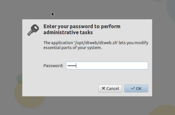
Insert the root password ( udooer by default )
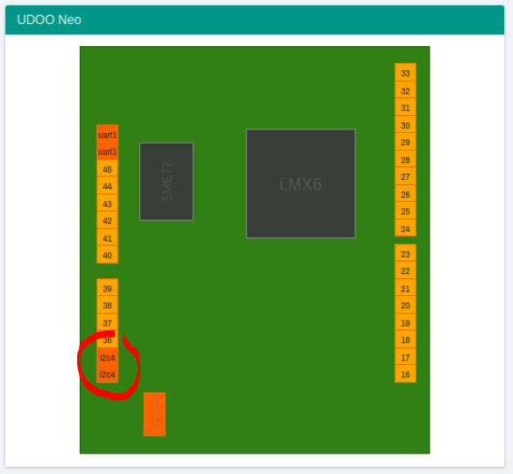
The tool shows all the A9 pins and their functions.
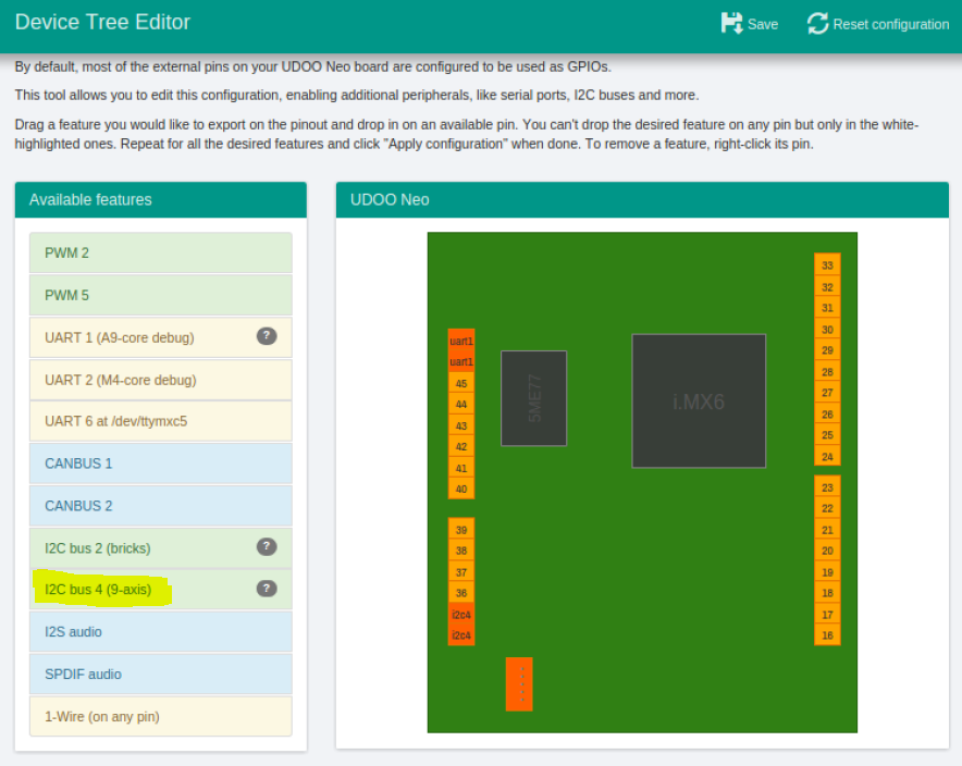
By default the i2c4 channel is highlighted and it means that is assigned ti A9.
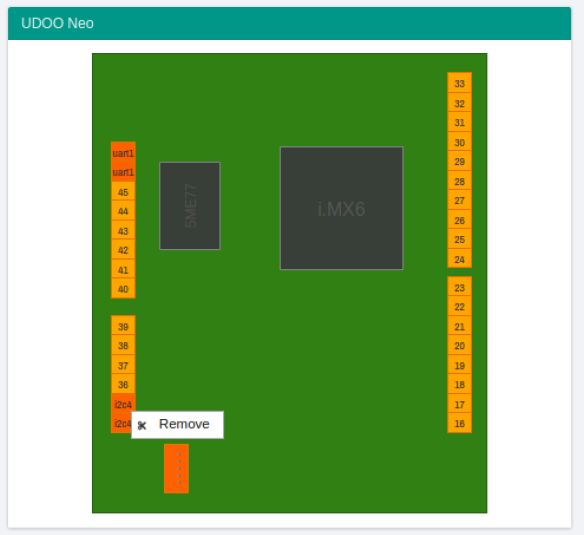
Right click on the pins and select remove
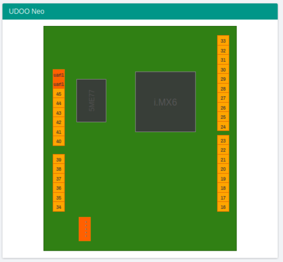
After that the i2c4 pins are not highlighed
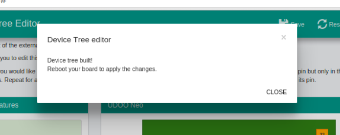
Click on save button on the top bar.
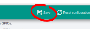
Click ok, close the browser and reboot the board.
For an example sketch of how to catch data from the motion sensors through Arduino M4 go to the Controlling 9-axis motion sensors section.